
Dipl. Ing. (FH), Electronics Engineer,
High Frequency
Born 1927
http://www.mydarc.de/DL6QA
E-Mail: dl6qa(a)darc.de
On the air since 1950
KCJ # 391
 |
Author:
DL6QA - Fred Dipl. Ing. (FH), Electronics Engineer, High Frequency Born 1927 http://www.mydarc.de/DL6QA E-Mail: dl6qa(a)darc.de On the air since 1950 KCJ # 391 |
This script has been compiled after several test transmissions from Swedish VLF Station Grimeton (SAQ) on 17,2 kHz since March 2009 preparing for special transmissions on May 19 th and 20 th, 2009 when the Japanese VLF Station Yosami Radio/JND will be nominated to Institute of Electrical and Electronics Engineers (IEEE) Milestone and also to commemorate and celebrate its start 80 years ago.
VLF Propagation
All active radio amateurs interested in DX are well informed about the complex short wave radio propagation processes involved during a QSO. However, this article principally concerns the propagation of VLF and LF and is for readers interested to know more about the slightly different behaviour in contrast to short wave propagation and who would like to receive and monitor VLF or LF transmitter signals.
There are a few software programs available for receiving VLF and LF signals via the soundcard of a PC. Each of these programs have their advantages and disadvantage. Very recommendable is the software program Audio Spectrum Analyser “Spectrum Lab” of OM Wolfgang Buescher, DL4YHF (Wolf). Also I recommend to visit the homepage of IK1QFK, Renato Romero “Radio Waves below 22 kHz”. For more details please visit both URLs in the Annex below, which also includes a selection of a few Radio Propagation programs.
Radio propagation in the earth's atmosphere is affected by the daily changes of ionization in upper atmosphere layers due to the sun. X-rays and short ultraviolet radiation (UV) from the sun ionize air molecules in the upper atmosphere forming what is called the "ionosphere". The free electrons from ionized molecules are responsible for the fact that radio transmissions of short and long wavelengths (approx. 10 m to many km) can be received over very wide distances far beyond the horizon. The ionosphere is composed of several layers of higher and lower concentration of free electrons called the F- (F1-/F2-), E- and D-layers. The F-Layers at heights of approx. 150 to almost 1000 km are mainly responsible for short wave radio propagation . The F1-Layer is sometimes present in daylight at a height of 220-230 km. It is not a stable reflector. At night it increases in height and merges with the F2 Layer to form the night-time F-Layer at heights between 280 and 320 kM. The F2-layer in daytime is the so called DX workhorse. This layer varies in height between 350 and 450 Km. Higher in summer than in winter. Higher at the peaks of the sun spot cycle.
The E-layer can be found at heights between 100 and 130 km.
When a radio wave leaves an antenna it spreads out in all directions if the transmitting antenna is an omnidirectional antenna. Part of the radiated energy travels along near the ground and is guided around the surface of the earth much as electromagnetic waves are guided by wires. This portion of the radiation is called ground wave or surface wave. The remainder of the energy is called sky wave or space wave. It is radiated upward into space and would be lost completely were it not for the different reflecting layers of ions and electrons that exist some 30 to almost 800 km above the earth’s surface. These different layers can reflect or refract a portion of the incident radiation back towards the earth and produce signals at distant locations from the transmitter.
The characteristics of the ionosphere go through regular variations which affect the propagation of radio waves. These variations today can be predicted with fair accuracy. They are of three principal types, so called
Moreover, radio propagation is also influenced by the strong earth’s magnetic field.
During daylight, the sun's ionizing radiation penetrates deep into the ionosphere, producing enough free electrons at altitudes down to almost 30 km allowing radio waves to reflect from that region. But the air density (concentration) of air molecules is still relatively high at that altitude, so the electrons very soon lose energy through permanent collisions with prevailing air molecules resulting in a lot of energy absorption.
Understanding VLF Propagation
VLF propagation is quite more complicated as it is sometimes modelled.
The lowest layer of the ionosphere is the D-layer which begins at about 40 to 90 km altitude. In contrast to the other layers this D-layer has stronger attenuating characteristics as well as absorption effects depending on the radio frequency, especially on VLF (very long), LF (long) and MF (medium) radio wave radio propagation. The D-layer fortunately disappears shortly after sunset in those regions that enter the semi-darkness and darkness shadow areas of the earth. These areas are known as the so called grey line. However, after sunrise, when ionization effects of solar x-ray and UV become stronger the attenuating D-layer again takes over the reflecting characteristic of the E-layer. Therefore VLF, LF and MW radio waves coming in from long distances after sunrise are damped and ground wave propagation predominates. Shorter waves are more able to penetrate the D-layer since they cause smaller collision rates with air molecules at lower heights. The radio signals cause the free electrons in the D-layer to vibrate. As they vibrate, the electrons collide with molecules, and at each collision there is a small loss of energy. But as radio waves in the range of 10 kHz to approx. 1 MHz are reflected mainly by the E-layer and also F-layers their field strengths will only reach a maximum in the darkness as soon as the D-layer gets weaker and disappears. At night the electrons in the lowest regions dissipate by recombination and thus the layer becomes transparent to radio waves. Reflection then takes place from regions at 80 km altitude and above, but with lower absorption due to the longer mean free path of electrons in the lower air density. Long distance paths improve, while signals from closer transmitters may reduce.
The grey line or terminator line is a transmission region between daylight and darkness. One side of the counter clockwise rotating earth is coming to sunrise, and the other approaching sunset. This terminator is a somewhat diffused region because the earth’s atmosphere tends to scatter the sun light into darkness. Especially those sun rays hitting the top regions of the atmosphere. The sun rays enter and leave the atmosphere unless they strike the earth. Remember that sun rays are a parallel light source due to the far distant sun. Sun rays are never “bent”. Propagation along the grey line is very efficient because greater distances can be covered than might be expected for the frequency in use. One of the major reasons is that the D-layer, which absorbs frequencies from VLF to HF, disappears rapidly on the sunset side of the grey line, and has not yet built up on the sunrise side.
The very low frequency part of the radio frequency spectrum (VLF, 3 to 30 kHz) is characterized by a low attenuation rate, high phase and frequency stability, and high signal to noise ratio. Therefore, VLF radio propagation is used for many practical applications, e.g. frequency standardization, clock synchronization, radio navigation beacons, reliable long-distance radio communications. VLF was formerly also applied for the detection of nuclear explosions. This reconnaissance has now mainly been taken over by military satellites. Concerning nuclear explosions below an altitude of about 15 km they have little effect on radio wave transmissions. However, a detonation occurring at an altitude between 15 to 60 km can produce blackout in the low-frequency, medium–frequency, and high-frequency bands over a radius of several hundred kilometres. This effect lasts only for a few minutes except in an area close to the site of the nuclear explosion.
As VLF waves can also penetrate water to a depth of roughly more or less 10 m to 40 m, depending on the VLF frequency employed, on the salinity of the water as well as on the temperature of the water. VLF is also used for very long-distance radio communications with submerged submarines near the surface. But this is not the topic of today as it is a most complex matter. However, water as a reflecting and/or conductive media (reflective mat) is also important for the vertical polarized ground propagation of VLF.
Commercial VLF radio stations mainly apply very high power transmitters ranging from 5 kW to 500 kW or more. Due to the excellent ground propagation properties of VLF when transmitted vertically polarized and the very long wave length, all transmitter operate very high antenna towers. Ground wave propagation is effected by the ground conductivity and the dielectric constant of the terrain. At 10 kHz the depth of penetration of VLF radio energy into the ground can be between 2.5 m to 150 m. The ground conductivity and the dielectric constant depends on the surface over which the ground wave propagates ( e.g. sea water - fresh water - dry, sandy flat coastal land - marshy, forested flat land - mountainous hills up to 1000 m - cities - etc.). This is a knowledge for itself and rather complex. Because the ground wave is attenuated so much at higher frequencies its chief usefulness lies in the long wave and broadcast (MW) bands. Daytime reception of broadcast radio stations is entirely by means of ground wave. The groundwave is always vertically polarized because any horizontal component of electric force would be shorted out by the ground. For this reason vertical antennas must be used for ground wave transmission as well as also for reception (vertically polarized receiving antenna).
Because of the low bandwidth available in the VLF band from 10 kHz to 30 kHz it is not possible to transmit audio signals, therefore most messaging is done with alphanumeric data at very low bit rates. For instance one of several methods used is to transmit in On-Off Keying or Continuous Wave Keying. These are very simple Morse code transmission modes where carrier ON = mark and OFF= space. This is also the simplest possible form of radio transmission, but it is rather difficult for transmitters to continuously transmit at high power levels, also the signal can easily be suppressed by atmospheric noise, so this is only really used for emergencies or basic testing. VLF stations therefore also use other code formats.
Considerable progress has been made in recent years in understanding more of the propagation of VLF and LF in the earth-ionosphere “waveguide”. A waveguide can be considered as a so called “duct” between the bottom side of the ionosphere and the earth’s surface . A prerequisite is that the very low frequency must be vertically polarized, the antenna of the transmitter as well as the antenna of the receiver. However, the bottom side of the ionosphere does not constantly have a smooth surface like a mirror and changes now and then. At daytime the D-layer is present in this duct, thus the D-layer in this case is the bottom side of the ionosphere. At night at darkness the D-layer as well as the E- and F layers slowly disappear more or less totally or predominantly.
Now and then, however, the bottom surface/edge of the ionosphere changes. When we talk about the bottom edge of the ionosphere this would in our case be the underside of the D-layer. At night the D-layer, the E-layer and the F2-layer break up (dissolve) totally or predominantly. The upper part of the waveguide now is the bottom surface (underside) of the F2 –layer. Now the reflecting properties of the waveguide change and consequently also the propagation conditions change for VLF wave according to the time of the day. If the transmitting VLF location is in the darkness zone of the earth and the radio wave arrives in the daylight zone, the amplitude in the semi-darkness zone slowly starts to be squeezed together and the wave will be extended in its length. By this the amplitude will reduce and the phase position of this signal will change causing a drop of signal strength.
Not only the diurnal course takes influence on the structure of the atmospheric waveguide. Also if there where an X-ray eruption of the sun or a particle break-in take influence on the ionosphere, the structure of the underside of the ionosphere changes . In this case it comes to uncontrolled amplitude and phase (timing) disturbances.
At short distances from a transmitter the received signal is chiefly by a ground wave or so called surface wave, and at very – low frequencies its intensity is essentially inversely proportional to distance. At greater distances the field intensity falls at a higher rate because of losses in the ground and because of the curvature of the earth. These losses increase with frequency. At sufficiently great distances the received level is chiefly due to sky waves reflected from the ionosphere. At intermediate distances the field is a combination of both sky and ground waves that “can” result in interference (fading) patterns.
The strength of the received VLF signal depends on the prevailing effective reflection coefficient of the region from which the radio wave reflects in its multi-hop duct path between earth and the ionosphere. In daytime the reflecting region is lower, the air density is higher, and the free electron density is controlled strongly by the solar radiation, etc. At night-time the reflecting region is higher, the air density is lower, and the free electron density is controlled by variable ambient conditions.
Summary
It may always be better to speak in terms of “regions” rather than “layers”. The lower air density in the higher reflection region at night results in a higher reflection coefficient with less absorption whereas the higher air density in the lower daytime reflection region results in a smaller reflection coefficient with more absorption. In the daytime lower levels the free electrons suffer more collisions per second than do the free electrons at the higher night-time levels so that the night-time“mirror” is brighter (less absorption of the VLF radio signal). Electron collisions with heavier air particles result in absorption of the VLF radio signal and the absorption depends on the collision frequency. Night-time fluctuations in signal strength are especially noticeable during and for sometime after geomagnetic storms when electrons somewhat erratically precipitate into the upper atmosphere from the earth’s radiation belts.
Electron density at night and noon versus altitude are as follows:
Let us for instance consider a situation that a radio amateur in JA in the very early morning hours on May 10 th is planning to receive a VLF transmission from SM. Local time in SM is 19:00 UTC. Japan is slowly moving in the direction to dawn and approaching sunrise, i.e. the Grey-Line:
At about 03:00 UTC local time the Island of Hokkaido slowly enters dawn (semi-darkness) and at 04:30 UTC full daytime sun. On May 15th the sun already continuously (24 hours) covers the complete area from the North Pole to Latitude 70:00 N, i. e. the sun already never sets in this area on this date. In Sweden at 19:00 UTC the sun is still present when it is 03:00 UTC in Japan but Sweden is slowly approaching the semi-darkness sunset zone. VLF transmissions from Sweden still have to overcome a short path of the squeezed together propagation waveguide (duct) as mentioned above before VLF propagation enters better conditions when the D- and E-layers have disappeared. Propagation then later takes place in full darkness to Japan but will be possible for about 15 to 20 minutes only because the northern part of Japan is already slowly entering the unfortunate squeezed together propagation waveguide (duct) but at the same time the sun rays already slowly start striking the very far distant upper atmosphere and are almost “scraping” the earths ground surface (semi-darkness zone), this means few sun rays are fortunately already “building up” the F-layer in the central and southern parts of Japan. The very unfortunate situation however is that at 04:30 UTC in Japan the VLF signal has to overcome more than about 30 % (!) of the long propagation path on the Asian Continent at daylight, causing a strong weakening of the VLF radio signal. Possibly strong deterioration of the VLF signal will latest start at 04:00 UTC. See propagation charts:
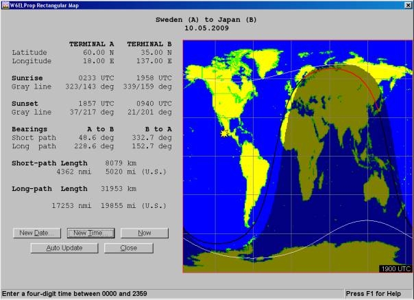
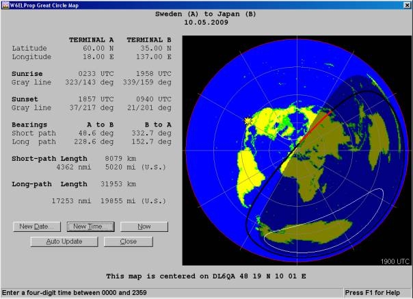
Grey line charts at 19:00 UTC. Propagation program W6ELProp.
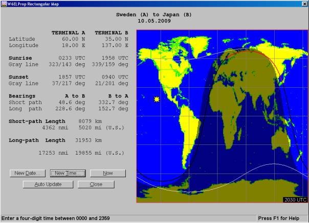
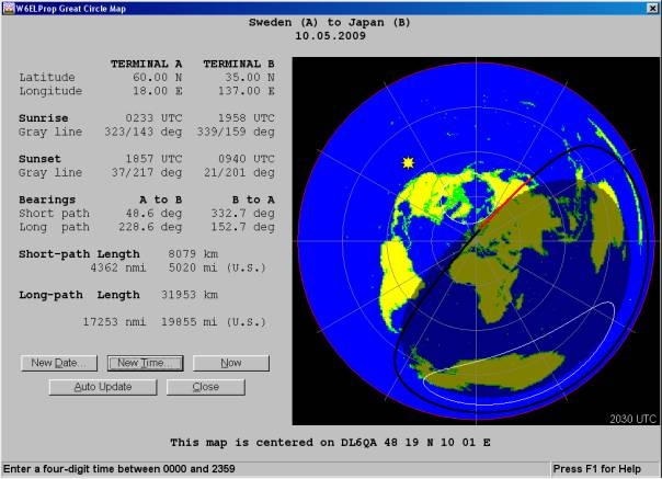
Grey line charts at 10:30 UTC. Propagation program W6ELProp.
Loop Antennas
An antenna that has very useful general and directional characteristics for VLF is a vertical polarized loop antenna. The dimensions of such an antenna are usually very small compared with a wave length, so that the currents are in phase all around the loop as shown below. To list all the various options possible in this publication would be an almost endless project. I recommend those radio amateurs interested in receiving loops to consult the Internet. Also directional active ferrite core antennas with multiple turns of insulated copper wire can be used for receiving VLF transmissions.
This is how a loop antenna functions:
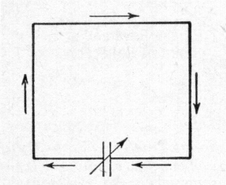
Currents in a single turn loop antenna.
The two vertical sides of a loop antenna are equivalent to two vertical antennas having a spacing that is a very small fraction of a wave length and having currents in opposite phase (one current is up when the other is down). The resulting horizontal pattern is a “figure eight” with zero line perpendicular to the plane of the loop. The top and bottom parts of the loop are equivalent to two horizontal antennas, also 180° out of phase so that their pattern is also a “figure eight” but this time vertical having its zero line perpendicular to the plane of the loop. This sharp null or so called zero-signal line makes the loop very useful in direction finding applications when receiving VLF signals. Sometimes this feature also considerably improves the signal quality if the loop antenna is positioned to the direction of the VLF transmitter.
DL6QA, May 2009
Annex
– General Propagation Software
See http://www.dxzone.com/catalog/Software/Propagation/
for various propagation software, for instance W6ELProp, DXPROP and many others.
W6ELProp is an excellent and a reliable radio propagation prediction program.
http://www.taborsoft.com/gawiz
GeoAlert-Extreme Wizard – “GEW” – is a powerful software
tool - for ham radio operators and SWL listeners - developed to maintain updated
geophysical indices and displays the information in a friendly – “at
a glance” - manner. GeoAlert-Extreme Wizard features numerous tools including
a “Global Maximum Usable Frequency” - MUF - map that creates, manages
and displays predictions from the VOACAP engine.
http://www.taborsoft.com/wwizard
WinCAP Wizard is the most powerful HF Communications Analysis Prediction package
ever developed. It was primarily developed for use in an amateur radio station.
WinCAP Wizard manages an enormous amount of data with a state-of-the-art database
and provides numerous unique and innovative "views" of VOACAP-propagation-prediction
information.
http://members.fortunecity.com/xe1bef/propa
gation.htm A very comprehensive homepage covering many propagation softwares.
http://areps.spawar.navy.mil
AREPS= Advanced Refractive Effects Prediction System. - Creation of Google Earth
display files. You do not need the Google Earth application installed on your
computer to use this feature - Specification of a numerical weather prediction
(MWP) data file and the forecast time to use for environmental data creation.
http://www.astrosurf.com/luxorion/qsl-review-propagation-software.htm
Review of HF propagation analysis & prediction programs , 54 programs at
a glance.
http://www.vlf.it/ IK1QFK, Renato Romero. Radio Waves below 22 kHz.
http://www.qsl.net/dl4yhf/spectra1.html Audio Spectrum Analyser “Spectrum Lab”.
http://www.qsl.net/dl4yhf/hamsoft1.html The Software Archive of DL4YHF.
http://www.vlf.it/submarine/sbmarine.html Reception of Submarine Communication Systems.
http://web.telia.com/~u33233109/saqrx/saqrx.html
A Soundcard Based SAQ VLF Receiver for All